A cheap CNC router you can build yourself. If you have a 3D printer, that is …
Having salvaged 6 NEMA23 stepper motors from some old HP printer/copiers, I had an itch that needed scratching – they simply had to be used for something. As they were a bit big for a 3D printer (another project), I thought that I would have good use for a CNC router in my workshop.
The goal was to get a cheap CNC router up and running, using my previous experiences with my Kossel Clear delta 3D printer, and also designing and building a larger delta 3D printer.
The goal was a sub $300,- CNC router, not counting the parts I had already.
Stuff I had
- 6 x NEMA23 motors
- Arduino MEGA + RAMPS1.4 board with DRV8825 stepper drivers
- 24V 5A powersupply (or 2 x 12V 35A in series after making them floating on the 12V side)
- White enclosure for the electronics
- Connectors and CAT5 cable
- Microswitches for endstops
Stuff I needed
- 3 x 4040 Aluminum extrusions 110cm (€15 each)
- 1 x 4080 Aluminum extrusions 30cm (€7)
- 30-40 x 8mm t-slot fasteners and 4mm bolts (€15 total)
- 12 x 12x6mm bolts with flat head (for X to Y adapter fastening and for Z-carriage to 4080 extrusions)
- 3 x 1M M10 threaded rod + 1 x 30cm M10 threaded rod (€12 total)
- 22 x M10 nuts (€5)
- Solid State Relay (€5,- eBay)
- 20 x 26x10x8 (6200ZZ) bearings from ebay (€10-20,- cant remember, they were cheap, also eBay)
- Base plate to mount everything on – MDF 1220x2440x22mm (€60,- local shop)
- Router (€60,- eBay)
- Lots of custom 3D printed parts (€40,- approx 2kg including prototypes and fumbles)
- My wifes patience and forgiveness (can´t be bought, but was granted)
Everything above is UNVERIFIED and from memory. Please plan accordingly if you try to duplicate this.
Here is what I ended up with ….
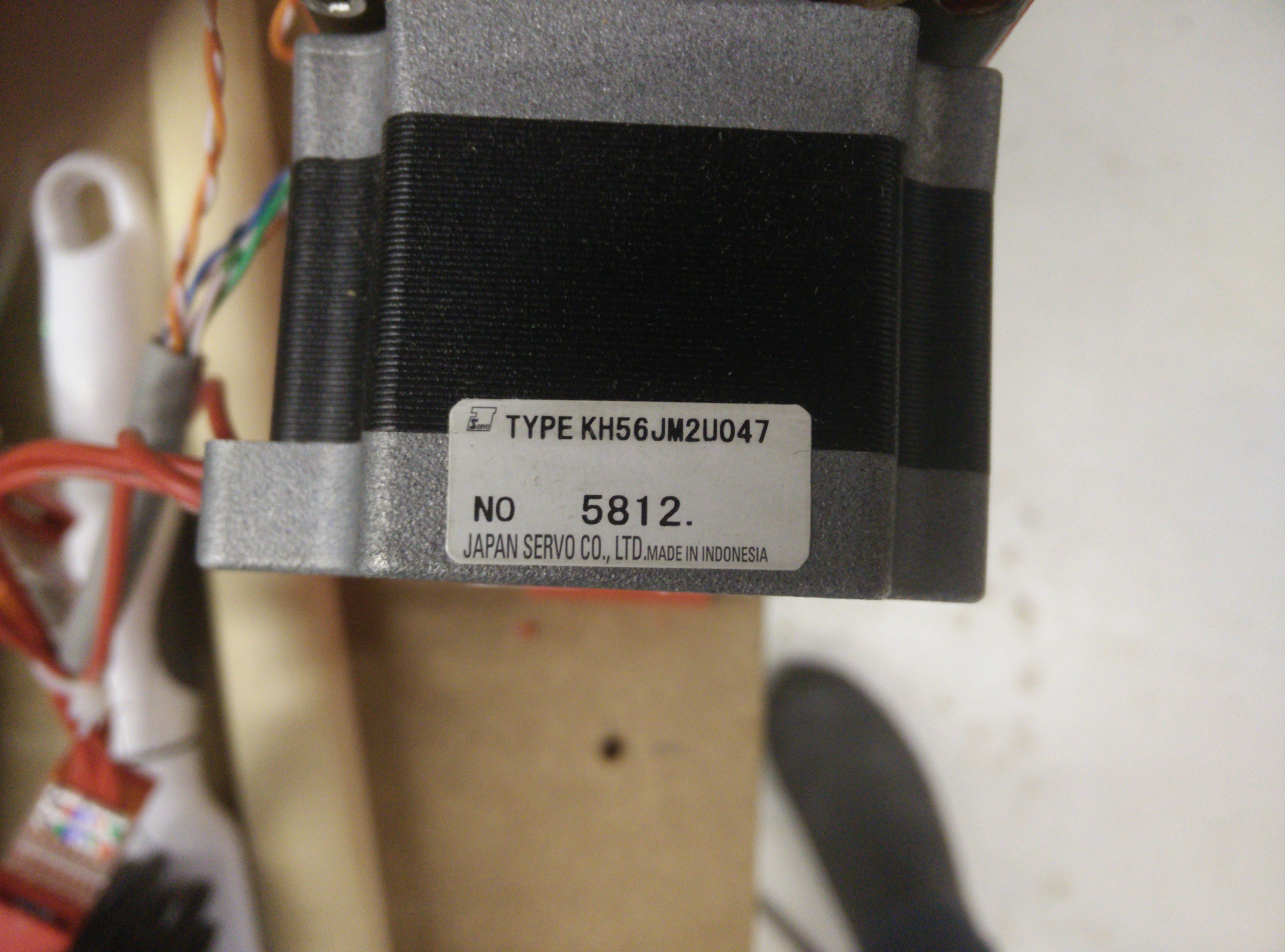
This is the one of the motors that started the project. An unspecified NEMA23 motor, 1.8degree steps and probably beefy enough for my purpose.
 This is the router I bought off ebay, it’s 850W 11-33KRPM, with a nice 44mm mount. It came as a complete router kit, with mount etc. for hand use, but I only needed the motor. Also it included a 6mm and 8mm chuck. I’ve ordered a 6 to 3mm converter on ebay, so I can use Dremel bits.
In the background you can see the Z-carriage being printed on my 3D printer.
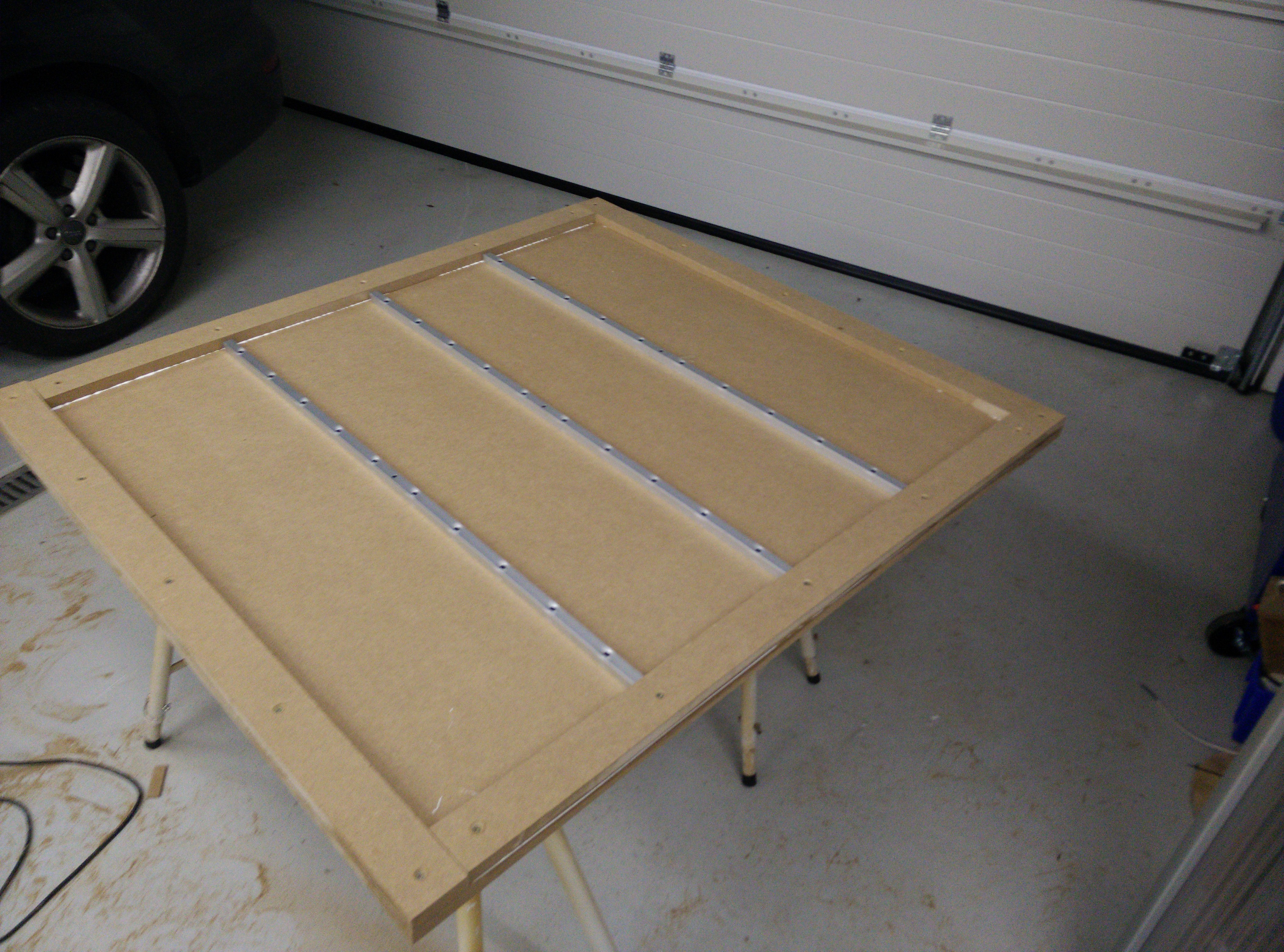 This is the base plate for the CNC router, turned upside down. It’s 1220x1220mm.
I cut some 9cm wide MDF parts and glued/screwed them onto the sides to make the base more rigid. Also I screwed on some 20x20mm square aluminum extrusions on, for even better stiffness.
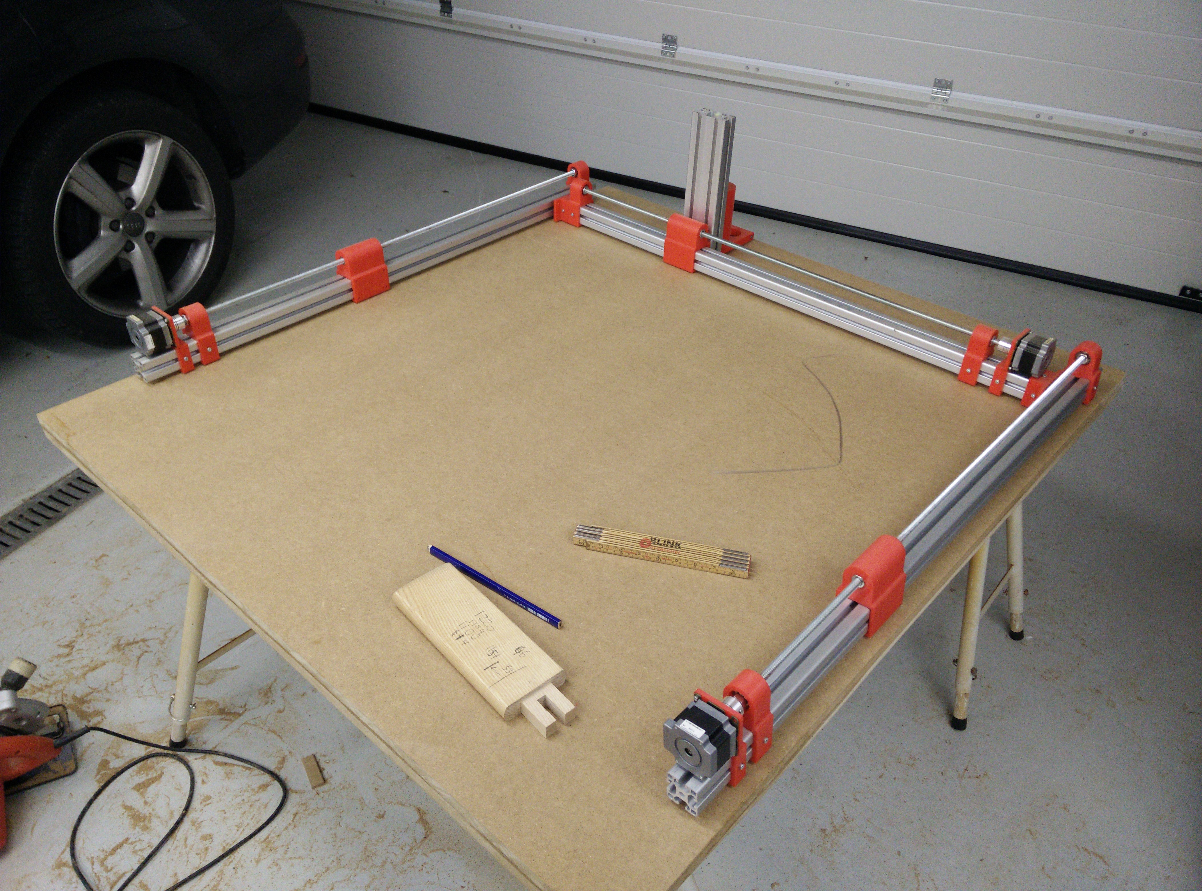
This is a basic layout of the 110cm extrusions mounted with motors, threaded rods, bearings and carriages. I have two Y-carriages and one X-carriage. In the background you can see the Z-carriage mounted, but the motor isn’t mounted there yet.
Both Y-axis mounted on printed bases, with threaded rod through base and into aluminum extrusions with T-slot connectors. I used M6 rod for this. Excuse the mess, but that’s how I work.
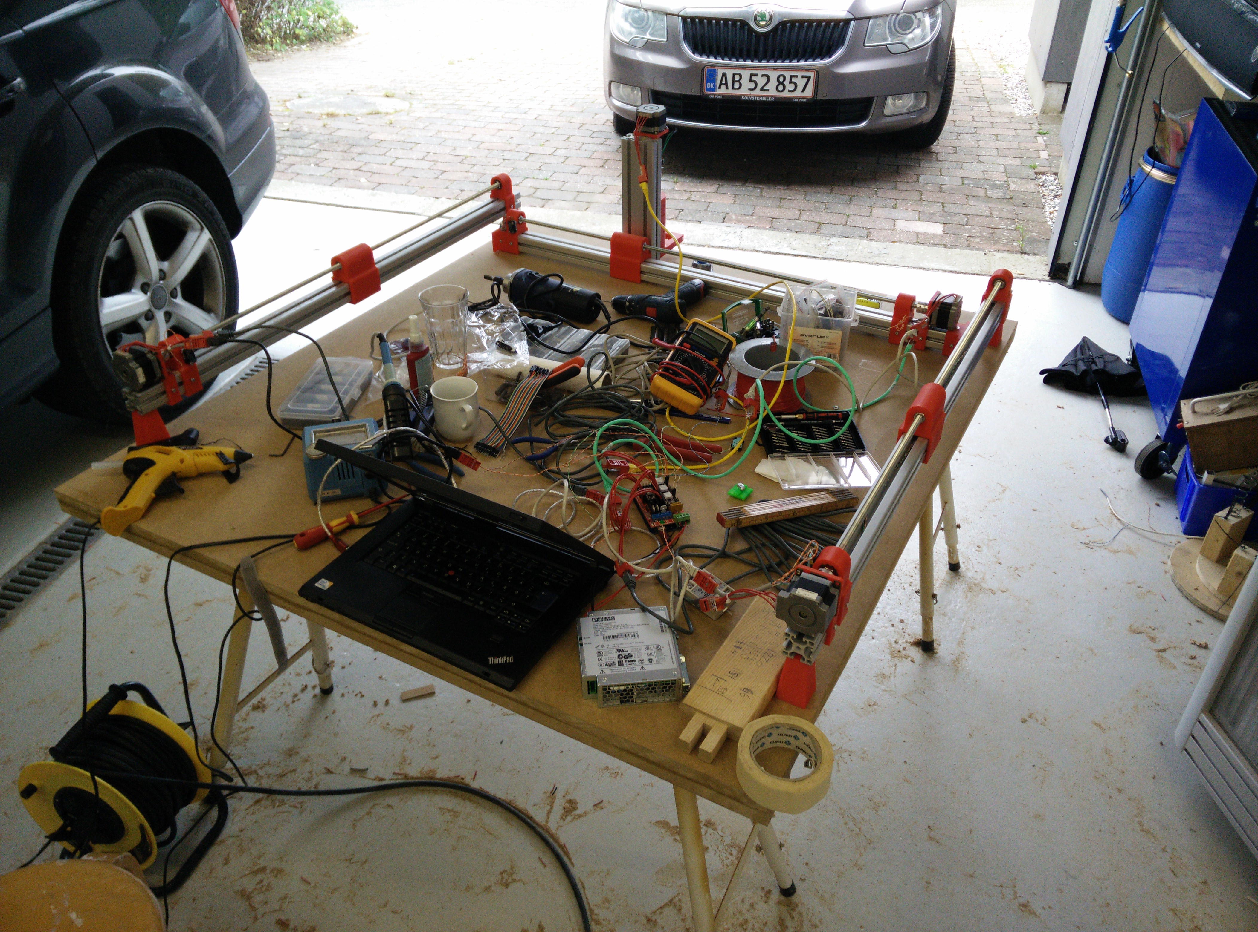
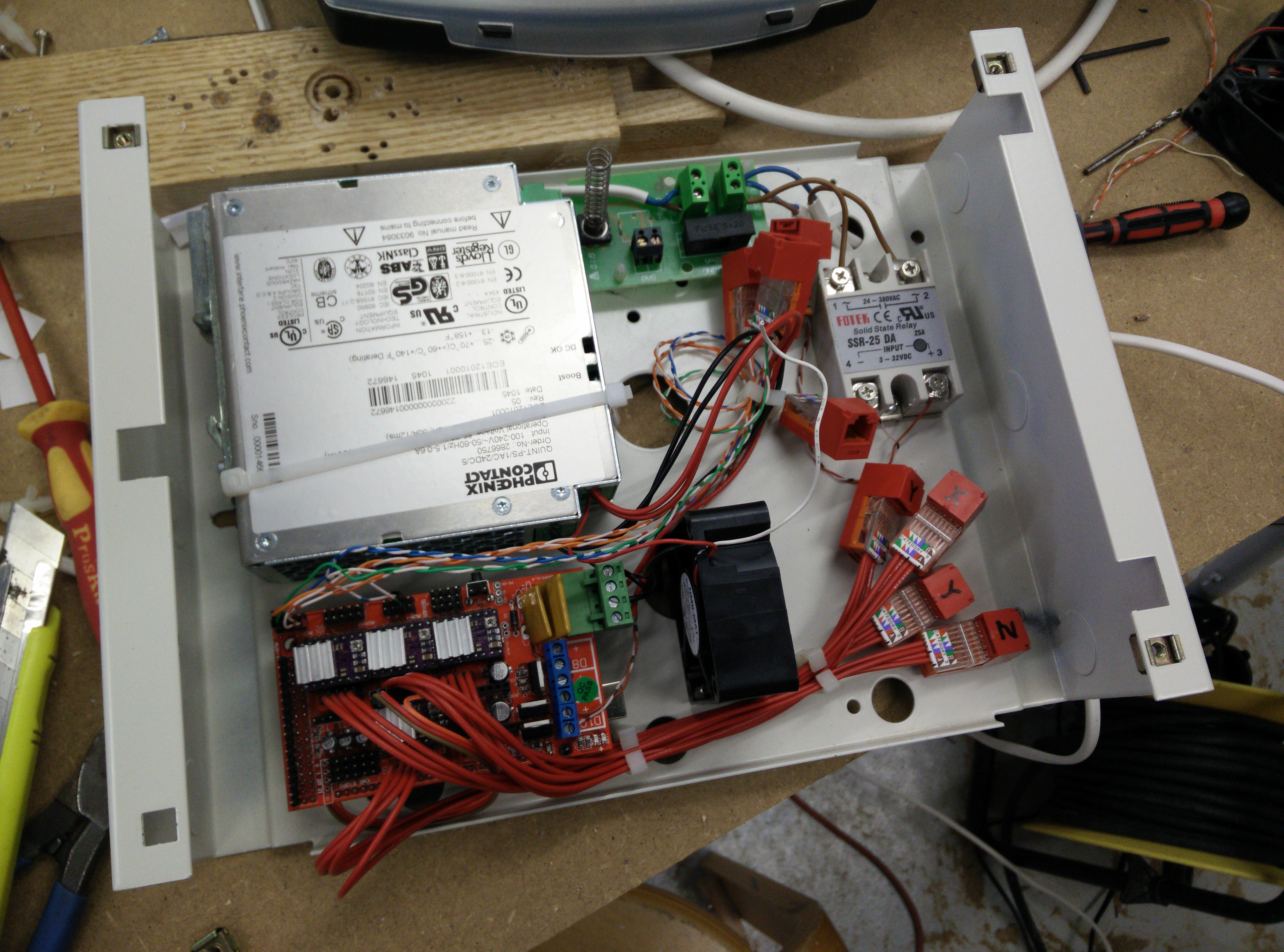 This i my bunch-o-wires setup. I’ve terminated everything in CAT5 connectors, as a friend gave me a bunch of used ones to play with. CAT5 cable is rated for 0.5A per wire, so I should be able to safely run 1.0A through 2×2 wires. Obviously I’m running 2.2A on them, and that seems to work. Assume nothing I guess. In the box, the red wires are for the motors, and the CAT5 are for logic (endstops).
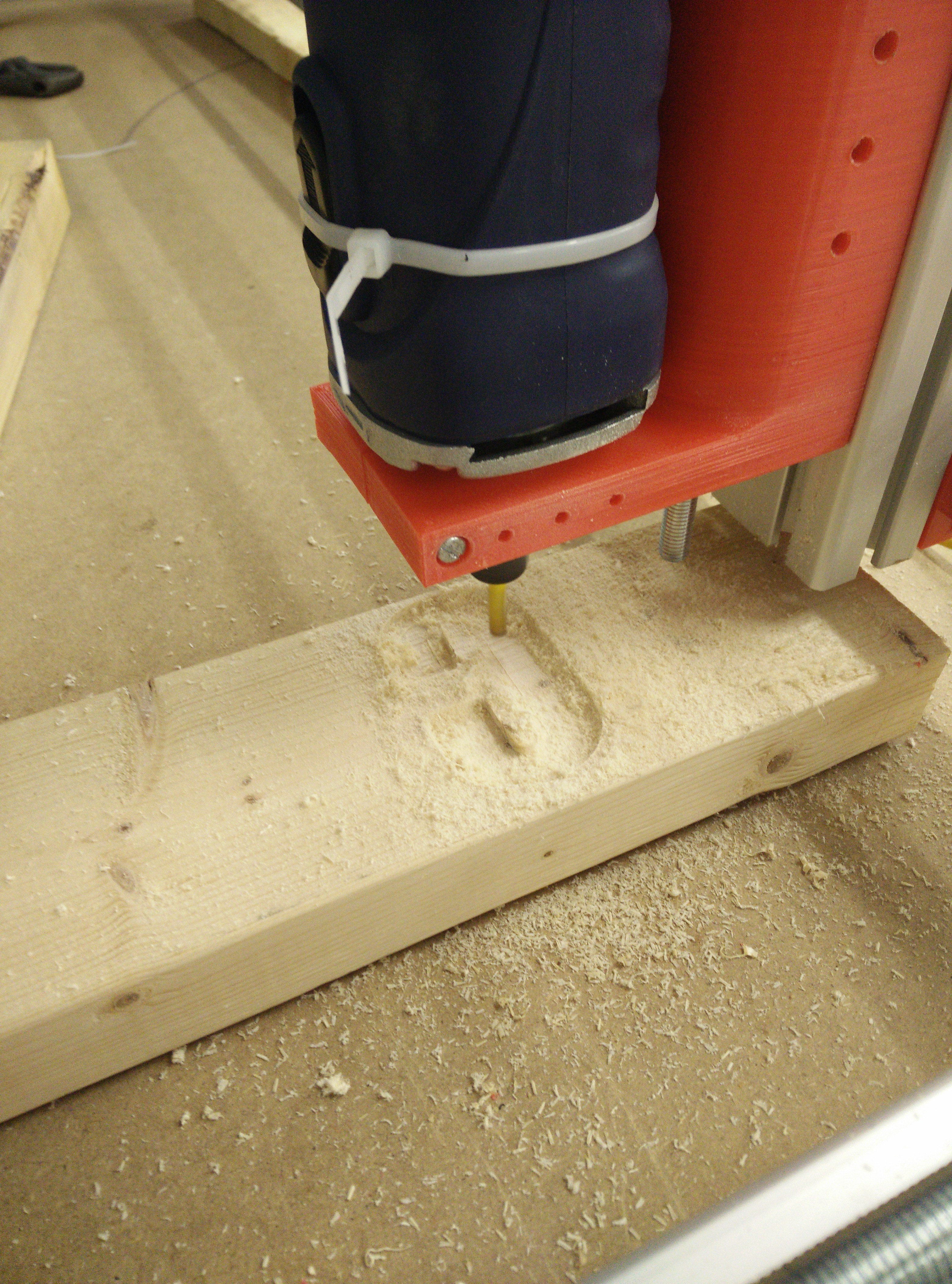
First run! Everything worked as expected …. except the Z-axis. The Z-carriage is sticking too much to the extrusions, and the stepper has problems pulling the Z-carriage up in a reliable fashion.
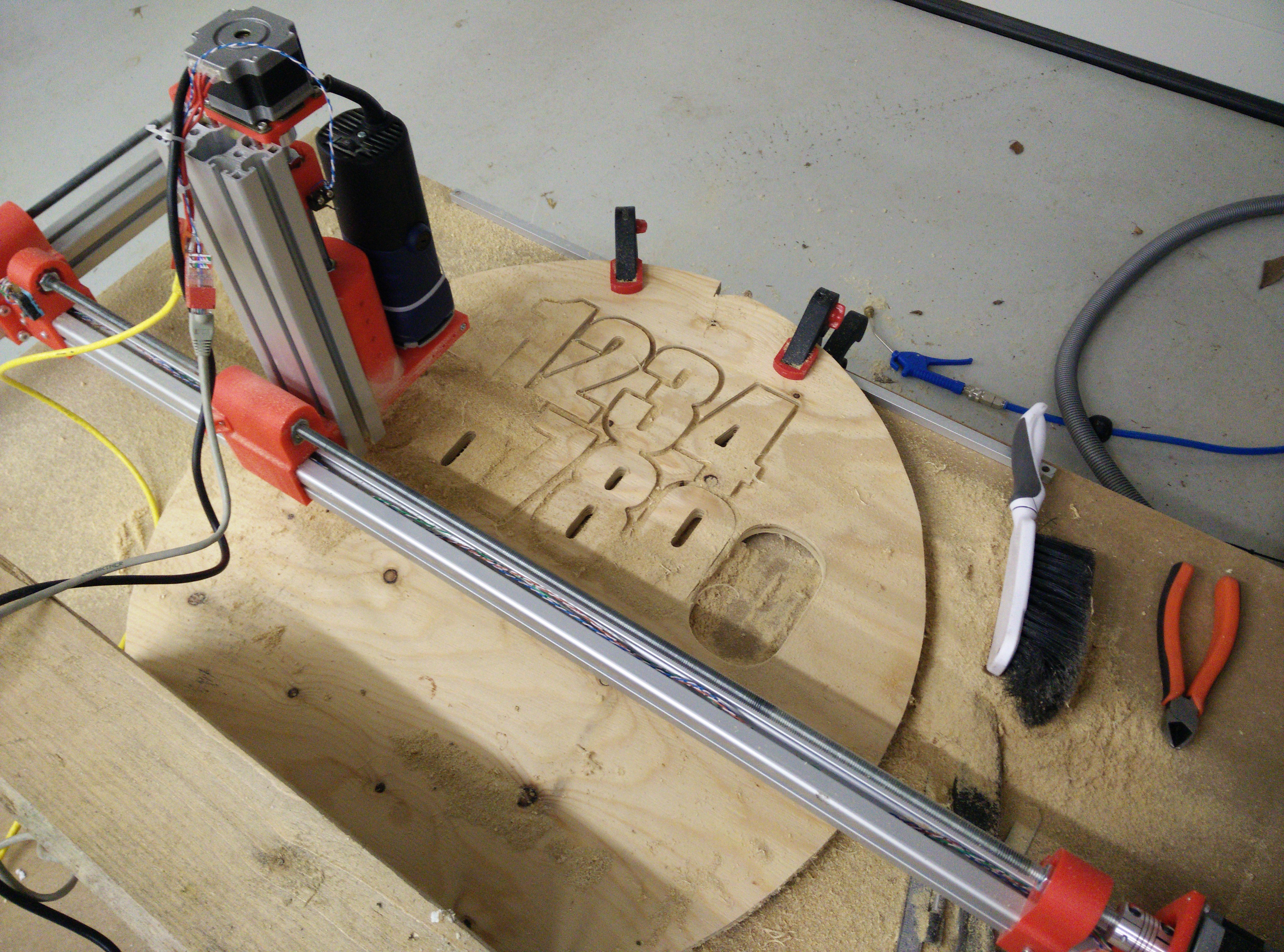 After some minor adjustments, I tried cutting some numbers out. That went well, except for the 3 and 8 not getting cut apart, because I placed them too close together. Ah, a learning experience this is 🙂
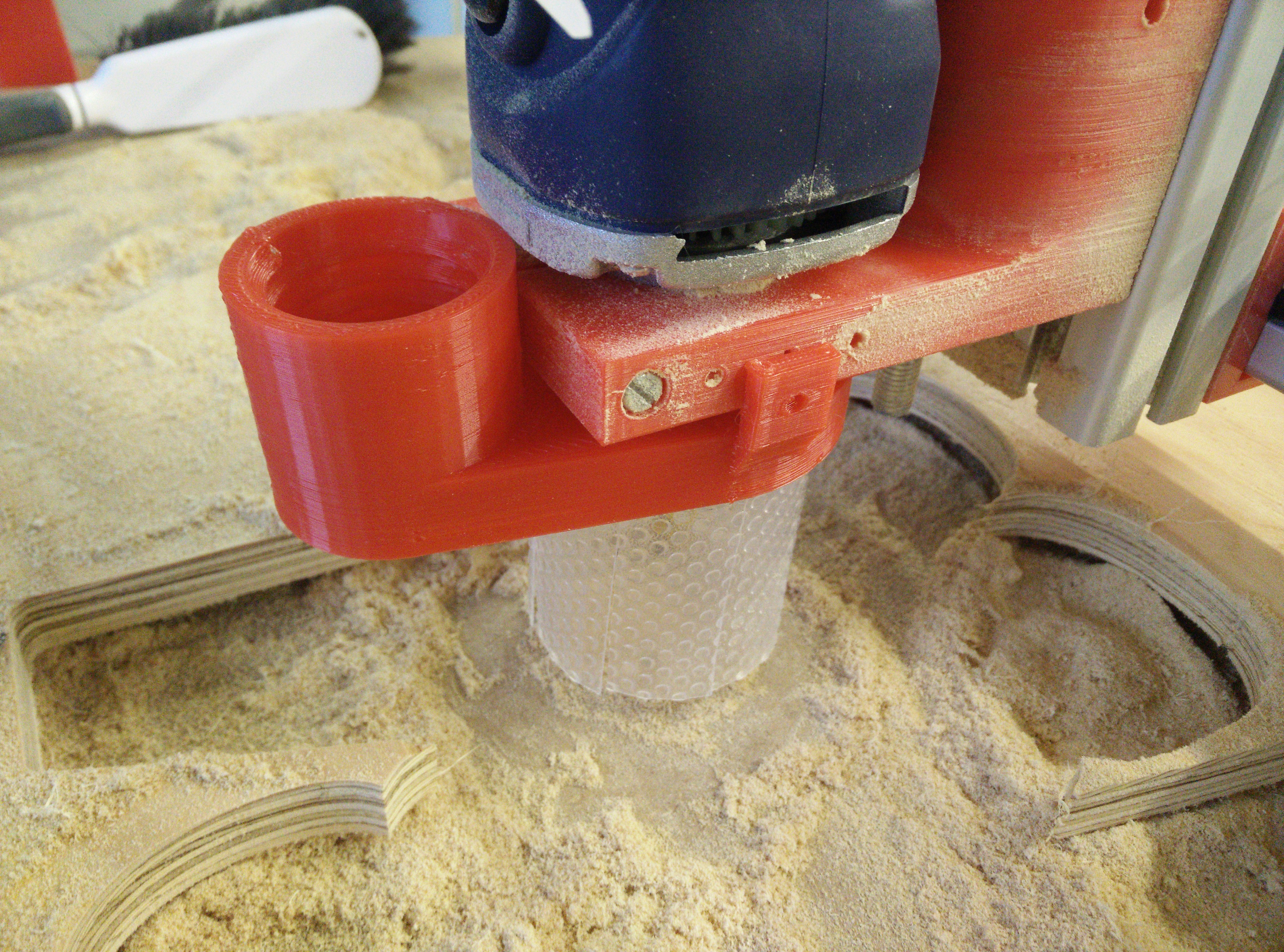 Dust shoe. Highly needed, as my threaded rods were getting gummed up with sawdust quickly.
STL files are HERE. Everything was printed in PLA with 0.25mm layer height, 40% infill. The Z-axis part took almost 12 hours, but came out perfectly first time (it weighs 250 grams).
Feel free to comment below.
Hello ! Please you would like to send me the motor wiring diagram KH56JM2U047 Thank you!
I have noticed you don’t monetize your site, don’t
waste your traffic, you can earn extra cash every month
because you’ve got high quality content. If you want to know how to make extra $$$, search for:
Boorfe’s tips best adsense alternative